ME 3901 Engineering Experimentation
Mechanical Engineering Department
Worcester Polytechnic Institute
Vibrations Measurements
· General System
· Mechanical Effects
Vibration Measurements
Mechanical Vibrations:
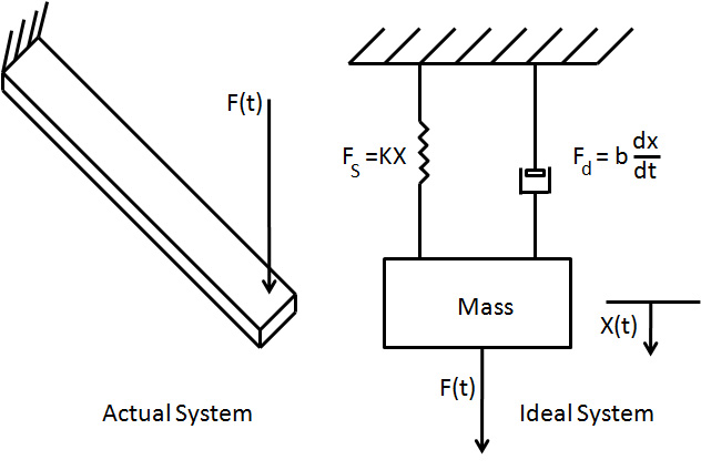
Vibrations are introduced using a cantilever beam as an example. The governing equations and derivations are valid for numerous vibrating systems.
Consider a Cantilever Beam:
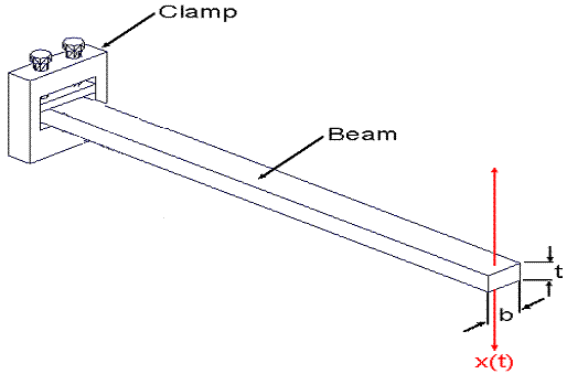
The deflection (in x direction) is:
![]()
where L is the beam length and y, the distance along the beam. In a static situation a dial indicator could measure the deflection (x) as a function of applied load (F).
A general system in differential form can be expressed as:

We are generally interested in:
Zero Order Systems: ![]()
First Order Systems: 
Second Order Systems: 
In Static Systems – the physical quantity is at rest, i.e. it is not changing with time (a zero-order system). If one were to rearrange a zero-order system:

The constant (![]() ) is called the static sensitivity. For the situation of a deflecting cantilever beam the static sensitivity is: (See previous equation for deflection.)
) is called the static sensitivity. For the situation of a deflecting cantilever beam the static sensitivity is: (See previous equation for deflection.)

Rearrange a first-order system:

Where the coefficient ![]() is known as the “time constant”.
Consider a step function behavior where F=0 for t<=0; X = XO for t <=0; and F=P for t>0.
is known as the “time constant”.
Consider a step function behavior where F=0 for t<=0; X = XO for t <=0; and F=P for t>0.


The half life of a response is when t = the time constant (Tau) The rise time of a response is defined specifically as the change in time required for the system to pass from 10% to 90% of its final response.
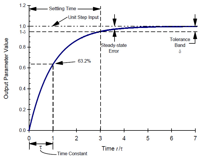
First Order Response Behavior
(Hong & Tessmann, "What Time Do You Have?",
Presented: Inter. Fluid Power Expos. & Tech Conf. 4/96)
Using this information one can look at our temperature lab measurements and determine the time constant of a thermocouple immersed in a liquid, for example.
Return to the cantilever beam.
If the beam is deflected and then released, it will oscillate or vibrate, that is the deflection varies with time and becomes more difficult to measure. It is a second-order system and can be described as periodic.
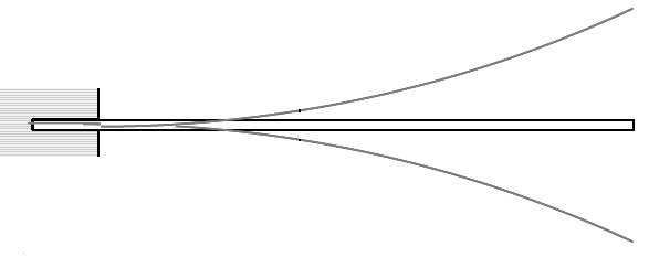
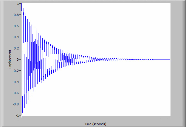
If a strain gage were attached to the beam it would generate a sinusoidal voltage output. The output amplitude would be proportional to the strain and a period inversely proportional to the frequency of vibration. Left to vibrate freely, without applied external forces, the beam will vibrate at its natural frequency, ![]() , and its amplitude of the response will decrease with time, as energy in the system is lost.
, and its amplitude of the response will decrease with time, as energy in the system is lost.
The natural frequency can be quantified as:

where (![]() ) is the mass per unit length of the beam. The constant Cn is coefficient for the different resonant modes = 3.516 for the first mode, and 22.4 for the second mode.
) is the mass per unit length of the beam. The constant Cn is coefficient for the different resonant modes = 3.516 for the first mode, and 22.4 for the second mode.
Example: Consider a beam with a width of 1cm and thickness of 2mm. Assume the density ![]() and the modulus of elasticity (
and the modulus of elasticity (![]() ). Let L vary from 0.2m to 0.5m What is the range of natural frequencies? The moment of inertia can be expressed as:
). Let L vary from 0.2m to 0.5m What is the range of natural frequencies? The moment of inertia can be expressed as:

Giving a flexural rigidity (EI):
![]()


More formally, we are examining a 2nd order ordinary differential equation of the form:

Let a2 = m (mass), a1 = b (damping coefficient), and a0 = K spring stiffness:

Recall:

Dividing through by the mass:

and making the variable substitutions:

The F=ma can be written in the form frequently used for dynamic analyses:

If the external force F(t) is not zero, then one has a forced vibration system. A free vibration system is when the external force is zero. The latter situation is of interest to us, specifically.

The solution of displacement (X) will be of the form:
![]()
where the exponential constants (m1, m2) involve the term ![]()
The nature of the displacement response will be dependent upon this term. There are 3 possible behavior modes:

Consider an overdamped system:

![]()
This system will not oscillate.
![]()
![]()
![]()
Consider a Critically Damped situation:
![]()
![]()
Sometimes written as:

At critical damping:

![]()
![]()
bc (the critical damping coefficient) provides the minimum damping that results in non-periodic motion.
Finally, consider an under-damped system:
![]()

Or

![]()

The displacement amplitude decreases with time, creating the exponential envelope. The logarithmic decrement, ![]() , quantifying the exponential decay can be obtained by measuring two displacements separated by n number of complete cycles via:
, quantifying the exponential decay can be obtained by measuring two displacements separated by n number of complete cycles via:


(http://www.mfg.mtu.edu/cyberman/machtool/machtool/vibration/damping.html)
with XO and Xn the amplitudes separated by n cycles. From the logarithmic decrement (![]() ), the damping ratio,
), the damping ratio, ![]() , are related:
, are related:

How did we get this expression? Consider the displacement formulation:
![]()


![]()


or the logarithmic decrement could be rearranged to express the damping ratio in terms of the logarithmic decrement.

and the variations continue for numerous expressions of all vibration terms:

There are numerous resources relative to this important topic. A summary plot of the behavior can be expressed as:
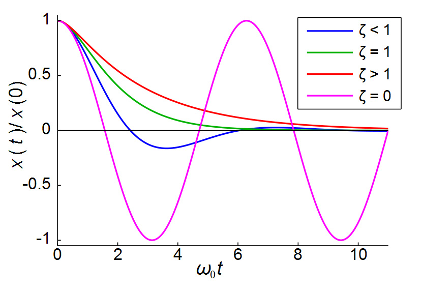
Which is from the wikipedia site on damping, the graph illuminates the behavior based on the damping ratio.